
![[Top]](../images/home.jpg)
![[Contents]](../images/contents.jpg)
![[Prev]](../images/previous.jpg)
![[Next]](../images/next.jpg)
![[Last]](../images/index.jpg)


MAX TNT Cabling and Connectors Specifications
This appendix describes specifications for different facets of the MAX TNT, and discusses cabling requirements. The appendix contains these sections:
Serial port specification
The serila port uses a standard DE-9 female connector that conforms to the EIA RS-232 standard for serial interfaces. All MAX TNT models use the RS-232 pinouts listed in Table D-1
.
Ethernet interface specifications
A MAX TNT installed with the Ethernet interface supports the physical specifications of IEEE l802.3 with Ethernet 2 (Ethernet/DIX) framing. It provides a single Ethernet interface and can support any one of the following Ethernet types:
Required equipment
To install the Ethernet interface, you must have the equipment described in the sections below.
Coax
You need a BNC T-connector. If your connection is at the end of a cable segment, you need a 50 Ohm terminator as well.
To install, attach a LAN BNC T-connector to the BNC port on the back of the MAX TNT. Use a standard 10Base-250 Ohm cable, such as RG-58 A/U or RG58 C/U.
 Caution: Breaking the LAN's continuity by inserting a cable segment or removing either of
the 50 Ohm terminations disrupts and disables the Ethernet.
10Base-T/100Base-T
You need a twisted-pair Ethernet cable and a dual twisted-pair cable terminated with RJ-45 modular jacks.
Use an EIA/TIA 568 or IEEE 802.3 10Base-T cable. Some installations require a crossover cable, as when connecting directly to the Ethernet port of a PC.
AUI
You need a transceiver and transceiver cable.
T1/PRI interface specifications
This section provides the specifications for the MAX TNT's T1/PRI interface and covers cabling requirements.
 Warning: To reduce the risk of fire, communication cable conductors must be 26 AWG or
larger.
 Warning: Afin de reduire les risques d'incendie, les fils conducteurs du cable de
communication doivent etre d'un calibre minimum de 26 AWG (American Wire Gauge), cest-
a-dire d'un minimum de 0,404 mm.
T1/PRI CSU requirements
Your requirements differ depending on whether a T1/PRI port on the MAX TNT is equipped with an internal Channel Service Unit (CSU).
Table D-2 lists CSU specifications
.
T1/PRI cable specifications
The maximum cable distance between the T1/PRI WAN interface equipment and the MAX TNT should not exceed 655 feet (200 m) for a MAX TNT without CSUs. Measure the line length and record it when you install the MAX TNT. You must specify this length when you configure the Line Profile parameters. For more information, see the MAX TNT Reference Guide.
Use only cables specifically constructed for transmission of T1/PRI signals. The cables should meet standard T1 attenuation and transmission requirements. The following specifications are recommended:
- 100 Ohm
- Two twisted pairs, Category 3 or better
The WAN interface cables and plugs described in the following sections are available for the MAX TNT's WAN interfaces.
T1/PRI crossover cable: RJ48C/RJ48C
Install this cable when the WAN transmits on pins 5 and 4 and receives on pins 2 and 1. Refer to Figure D-1 and Table D-3.

Figure D-1. RJ48C/RJ48C crossover cable
.
T1/PRI straight-through cable: RJ48C/RJ48C
Before installing this cable, verify that the WAN transmits on pins 2 and 1 and receives on pins 5 and 4. Refer to Figure D-2 and Table D-4.

Figure D-2. RJ48C/RJ48C straight-through cable specifications
T1/PRI straight-through cable: RJ48C/DA-15
Before installing this cable, verify that the WAN transmits on pins 3 and 11 and receives on pins 1 and 9. Refer to Figure D-3 and Table D-5.

Figure D-3. RJ48C/DA-15 straight-through cable
T1/PRI crossover cable: RJ48C/DA
Before installing this cable, verify that the WAN transmits on pins 1 and 9 and receives on pins 3 and 11. Refer to Figure D-4 and Table D-6.

Figure D-4. RJ48C/DA crossover cable
T1/PRI straight-through cable: RJ48C/Bantam
The WAN side of the cable connects to dual bantam jacks. Refer to Figure D-5 and Table D-7.
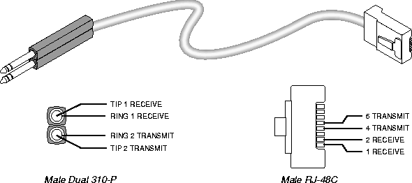
Figure D-5. RJ48C/Bantam straight-through cable
T1 RJ48C-Loopback plug
This plug loops the transmit signal back to the MAX TNT
.
T1/PRI WAN connectors
Table D-9 lists the pins on the T1/PRI WAN port used for Transmit and Receive. The remaining pins are not connected.
WAN switched services available to the MAX TNT
The MAX TNT is compatible with both AT&T and Northern Telecom central office switches, and can access all T1/PRI switched digital services offered by AT&T's ACCUNET Switched Digital Services:
- MCI 56 kbps and 64 kbps services
- Sprint Switched 56 kbps and 64 kbps services
- MultiRate and GloBanD (and GVPN in CCITT countries) PRI network services
Note: The MAX TNT can only access Switched-56 kbps services on a T1 access line or a
Switched-56 line.
For a listing of the compatible switch types, see the Switch Type parameter in the MAX TNT Reference Guide. In addition to switched circuits, the MAX TNT can connect to nailed-up circuits, and to aggregate nailed-up and switched circuits.
Serial host interface specifications
This section describes the cabling requirements, timing requirements, and interface types for the serial host ports on the MAX TNT.
The MAX TNT serial WAN ports are compatible with the following three electrical standards:
Selection of the proper cable between a serial host port and the serial device ensures:
- The proper mapping of pinouts from the MAX TNT to the application equipment
- Proper voltage levels
In the cable wiring tables that follow, the MAX TNT is the DCE (Data Circuit-Terminating Equipment) device, while the host equipment is the DTE (Data Terminal Equipment) device. The serial host interface cabling tables use the abbreviations listed in Table D-10. Note that the Send timing and Receive timing clocks are supplied to the host by the MAX TNT.
V.35 cabling
The pinouts for different types of V.35 cabling are listed in the sections that follow.
V.35/V.25 bis cable to Cisco
This cable connects the MAX TNT to the V.35 port of a Cisco router that uses V.25 bis dialing. It has the pinouts shown in Figure D-6 and Table D-11.
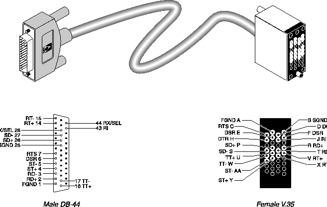
Figure D-6. V.35/V.25 bis cable to Cisco
V.35 cable to generic serial host
This cable connects the MAX TNT to the V.35 ports of a wide variety of equipment. A female-to-male V.35 gender changer is included when you order the cable. It has the pinouts listed in Table D-12.
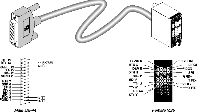
Figure D-7. V.35 cable to generic serial host
RS-449 cable to generic serial host
This cable connects the MAX TNT to the RS-449 ports of a wide variety of equipment. A female-to-male DB-37 gender changer is included when you order the cable. It has the pinouts listed in Table D-13.
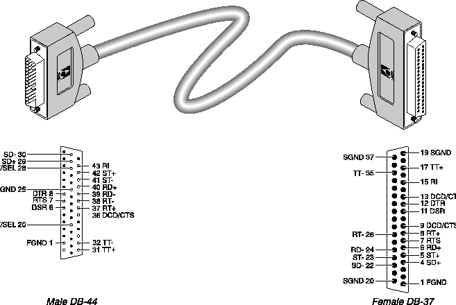
Figure D-8. RS-449 cable to generic serial host
.
Note: To manufacture an RS-449 cable for Cisco routers, use the above wiring list and
connect the following DB-37 pins to SGND:
- DSR- (pin 29)
- CD- (pin 31)
- CTS- (pin 27).
X.21 cabling
Ascend supplies a single X.21 cable.
X.21 cable to generic serial host
If your host is equipped with an X.21 interface, the host cable has the pinouts listed in Table D-14.
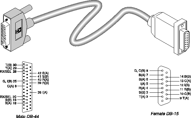
Figure D-9. X.21 cable to generic serial host
Cable length requirements
Table D-15 specifies the recommended maximum length of the cable between the MAX TNT and the serial host equipment. Longer distances at the specified data rates are possible when you use terminal timing, and still longer distances are supported by the installation of the Ascend RPM, a hardware device that provides an extended distance high-speed link between the MAX TNT and the serial host equipment.
Serial WAN cabling specifications
The MAX TNT unit's serial WAN interface supports nailed-up connections to the WAN. Data packets from the MAX TNT bridge/router module can use this interface, but bit streams from devices connected to the MAX TNT's serial host ports cannot.
The MAX TNT's serial WAN port is compatible with the following two electrical standards:
In the cable wiring tables that follow, the MAX TNT is the DTE (Data Terminal Equipment) that connects to a DCE (Data Circuit-Terminating Equipment) device through its serial WAN port. The MAX TNT receives the Send timing and Receive timing clocks from the DCE device.
V.35 cable to WAN
You connect a V.35 cable to the V.35 port of a DCE device. The V.35 cable has the pinouts described in Table D-16.
RS-449 cable to WAN
You can connect an RS-449 cable to the RS-449 port of a DCE device. The RS-449 cable has the pinouts described in Table D-17.
This section provides the cable specifications for the Ascend cable serial WAN cable (2510-0260-002).
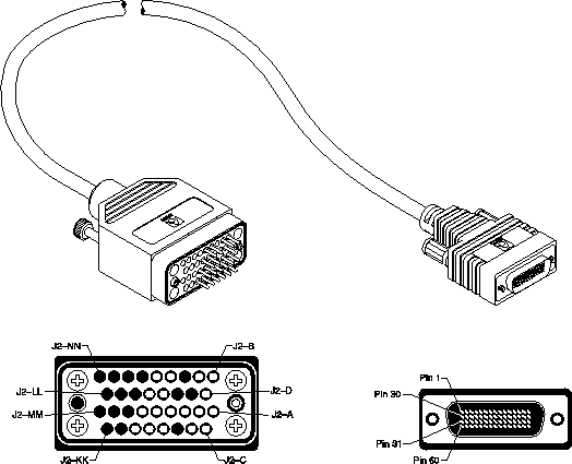
Figure D-10. Serial WAN cable
IDSL cable specifications
This section provides the specifications for the dual 50-pin telco to triple DB37 cable (2510-0311-002) IDSL cable.
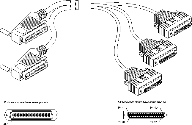
Figure D-11. IDSL dual 50-pin telco to triple DB37 cable
SDSL cabling specifications
This section provides the specifications for the 50-pin telco to dual DB37 cable (2510-0286-002) SDSL cable.
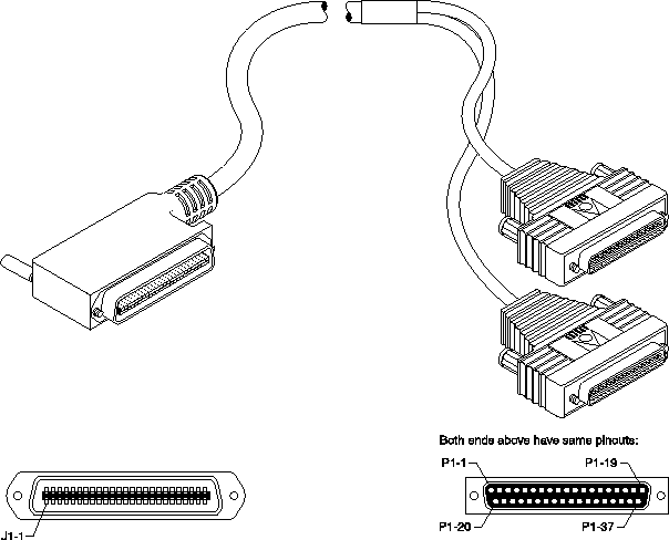
Figure D-12. SDSL 50-pin telco to dual DB37 cable
RADSL Cabling specifications
This section provides the specifications for the 50-pin telco to quad DB37 cable (2510-0305-002) RADSL cable.
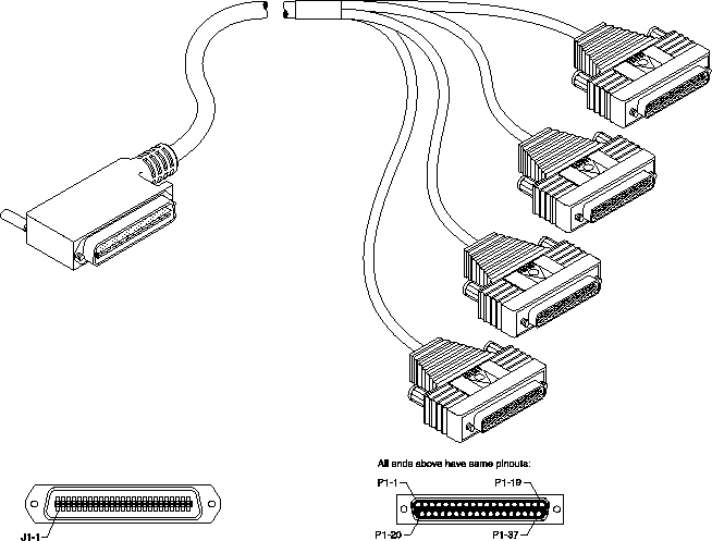
Figure D-13. RADSL 50-pin telco to quad DB37 cable
Slot card specifications
This section provides specifications for the MAX TNTslot cards.
T3 slot card specifications
The following table provides the specifications for the MAX TNT T3 card.
FrameLine slot card specifications
The following table provides the specifications for the MAX TNT FrameLine card.
Table D-23. FrameLine card specifications
|
Electrical
|
DSX-1 per ANSI T1.102 (DSX)
DS1 per ANSI T1.403, Pub 62411 (CSU)
|
|
Line Build Out
|
0dB, -7.5db, -15db, -22.5db (CSU)
0-133 ft, 133-266 ft, 266-399 ft, 399-533 ft, 533-655 ft (DSX)
|
|
Receive Equalization
|
Based on cable length and transmitter
|
|
Line Code
|
AMI, B8ZS
|
|
Line Rate
|
1.544 Mbps +/- 32ppm
|
|
Frame Format
|
Per ANSI T1.107a (M23 or C-Bit Parity)
|
|
Alarm Signaling
|
Red Alarm, yellow signal
|
|
Connectors
|
10 RJ45 (100 ohm line)
|
IDSL specifications
The following table provides the specifications for the IDSL card.
RADSL specifications
The following table provides the specifications for the RADSL card.
SDSL specifications
The following table provides the specifications for the SDSL line card.
![[Top]](../images/home.jpg)
![[Contents]](../images/contents.jpg)
![[Prev]](../images/previous.jpg)
![[Next]](../images/next.jpg)
![[Last]](../images/index.jpg)


techpubs@eng.ascend.com
Copyright © 1997, Ascend Communications, Inc. All rights
reserved.


