![[Top]](../images/home.jpg)
![[Contents]](../images/contents.jpg)
![[Prev]](../images/previous.jpg)
![[Next]](../images/next.jpg)
![[Last]](../images/index.jpg)


Configuring the RADSL Voice Splitter
This appendix covers these topics:
Introduction
Because the majority of residences and homes have only a single pair of wires installed between the telephone company's central office and the homes and that pair is already in use for voice services, it is important to integrate voice and data services over that existing single pair of wires to remain cost effective.
The MultiDSL voice splitter solution works in conjunction with Ascend DSLPipes to integrate Plain Old Telephone Service (POTS) with ADSL data. The MultiDSL voice splitter consists of the following components:
- The DSLVSP-a standalone splitter for the customer premises side
- The DSLVSO-a rack mountable version for the central office
RADSL operates between the 26 KHz and 1.2 MHz frequency spectrum. Voice calls operate between 300 Hz to 3,400 Hz. Because these frequency spectrums do not overlap, data and voice can be integrated onto a single pair of wires using RADSL. RADSL voice splitters simply filter out the RADSL data frequency and permit only the voice frequency to reach the central office switch for voice.
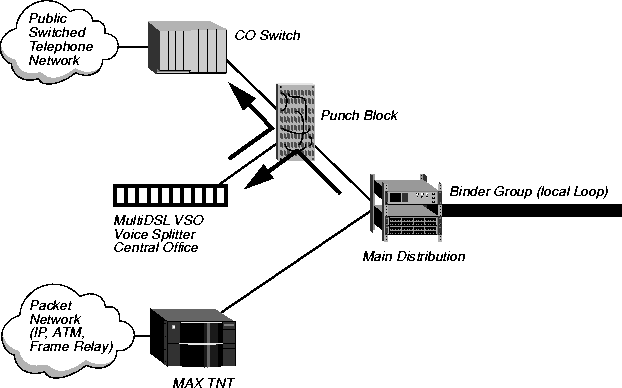
See Figure B-1 for an example central office RADSL voice splitter set up.

Figure B-1. Example central office RADSL voice splitter set up
The connection to the RADSL line card of a MAX TNT from the main distribution frame does not require a voice splitter at the central office side because the RADSL line card itself ignores the lower voice frequency spectrum and utilizes only the data spectrum.
DSLVSP for customer premises
The customer premises end of the voice splitter, the DSLVSP (Figure B-2), is installed at the demarcation point where the telephone company's local loop ends and where the inside wiring for telephones begins. Note that the DSLVSP for the customer premise is only available with the DSLPipe-C.

Figure B-2. DSLVSP
DSLVSO for the central office
The DSLVSO central office voice splitter (Figure B-3) consists of a rack and up to 24 voice splitter modules per rack.

Figure B-3. DSLVSO dimensions
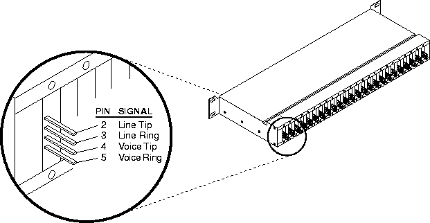
The rear of the rack contains pins for wiring up to 48 pairs of wires to a punch block. Of these pins, 24-pairs of wires are used for the incoming signals from the main distribution frame and the other 24-pairs of wires for connecting to the central office voice switch. See Figure B-4.

Figure B-4. DSLVSO rack pins
Installing the DSLVSP
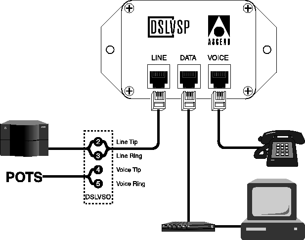
The DSLVSP has three RJ-11 connectors, each of which use pins 3 and 4:
- The connector labelled Line connects to the local loop to the central office.
- The connector labelled Voice connects to the telephone wires within the residence, which normally extend to every room for a phone connection.
- The connector labelled Data connects to the second pair of wires. This connects to the Ascend DSLPipe-C customer premises ADSL equipment for the data connection.
Figure B-5 illustrates a typical wiring set up.

Figure B-5. Example RADSL voice splitter wiring
Specifications
The RADSL voice splitter specifications are as follows:
The DSLVSO has a low pass frequency of 8 KHZ (US) or 20 KHz (International).
![[Top]](../images/home.jpg)
![[Contents]](../images/contents.jpg)
![[Prev]](../images/previous.jpg)
![[Next]](../images/next.jpg)
![[Last]](../images/index.jpg)


techpubs@eng.ascend.com
Copyright © 1997, Ascend Communications, Inc. All rights
reserved.


