
This chapter covers the following topics:
Filter overview
A filter contains rules describing packets and what to do when those packets are encountered. When a filter is applied to an interface, the MAX TNT monitors the data stream on that interface and takes a specified action when packet contents match the filter rules. Basic types of filters
Each Filter profile contains up to 12 Input-Filters (which are applied to inbound packets) and 12 Output-Filters (which are applied to outbound packets). Each of those specifications can be one of the following basic types of filters:
IP filters apply only to IP-related packets. They specify a forwarding action based on higher-level fields in IP packets, such as source or destination address, protocol number, and so forth. They operate on logical information, which is relatively easy to obtain.
IPX filters apply only to NetWare packets. They specify a forwarding action based on higher-level fields, such as source or destination network, node, and socket numbers. Like IP filters, IPX filters operate on logical information, which is relatively easy to get.
Route filters apply only to RIP update packets. They specify whether matching routes in a RIP packet will be accepted into the routing table or denied, or accepted with an increased metric. They can also specify a source address, to take an action on all updates from that address.
When you apply a data filter, its forwarding action (forward or drop) affects the actual data stream by preventing certain packets from reaching the Ethernet from the WAN, or vice versa. Data filters do not affect the idle timer, and a data filter applied to a Connection profile does not affect the answering process.
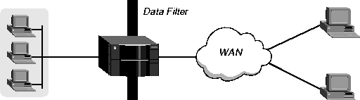
Figure 9-1. Data filters drop or forward certain packets
Call filters for managing connections
Call filters prevent unnecessary connections and help the MAX TNT distinguish active traffic from "noise." By default, any traffic to a remote site triggers a call, and any traffic across an active connection resets the connection's idle timer. 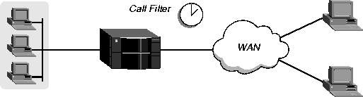
Figure 9-2. Call filters prevent certain packets from resetting the timer
Route filters for managing RIP updates
Route filters specify which routes in RIP update packets will be allowed to affect the routing table. They can also be used to increase the metric assigned to a route before adding it to the routing table.
How filters work
A Filter profile can specify up to 12 Input-Filter and Output-Filter rules. Each rule has its own forwarding action-forward or drop. The rules are applied in sequence, and a match occurs at the first successful comparison between a rule and the packet being examined. When a comparison succeeds, the filtering process stops and the forwarding action in that rule is applied to the packet. For route filters, the forwarding action has no effect, but another type of action in the rule is applied to the packet when a comparison succeeds.
Generic filters
In a generic filter, all parameter settings in a rule work together to specify a location in a packet and a number to be compared to that location. The Comp-Neq parameter specifies whether a comparison succeeds when the contents of the packet equal the specified number or when they do not equal the number. IP filters
In an IP filter, each rule includes a set of comparisons that are made in a defined order. When a comparison fails, the packet is allowed to go on to the next comparison. When a comparison succeeds, the filtering process stops and the forwarding action in the rule is applied to the packet. The IP filter tests proceed in the following order:
Following are the relevant parameters, shown with their default settings:
FILTER filter-name
      filter-name* = filter-name
      input-filters
            input-filters[1]-input-filters[12]
                  valid-entry = no
                  forward = no
                  type = generic-filter
      output-filters
            output-filters[1]-output-filters[12]
                  valid-entry = no
                  forward = no
                  type = generic-filter
Defining generic filters
Generic filters can match any packet, regardless of its protocol type or header fields. They use the following parameters, which are shown with their default values:
FILTER filter-name
      filter-name* = filter-name
      input-filters
            input-filters[1]-input-filters[12]
                  valid-entry = no
                  forward = no
                  type = generic-filter
                  gen-filter
                        offset = 0
                        len = 0
                        more = no
                        comp-neq = no
                        mask = 00:00:00:00:00:00:00:00:00:00:00:00
                        value = 00:00:00:00:00:00:00:00:00:00:00:00
      output-filters
            output-filters[1]-output-filters[12]
                  valid-entry = no
                  forward = no
                  type = generic-filter
                  gen-filter
                        offset = 0
                        len = 0
                        more = no
                        comp-neq = no
                        mask = 00:00:00:00:00:00:00:00:00:00:00:00
                        value = 00:00:00:00:00:00:00:00:00:00:00:00
gen-filterand the following packet contents:
offset = 2
len = 8
more = no
comp-neq = no
mask = 0f:ff:ff:ff:00:00:00:f0:00:00:00:00
value = 07:fe:45:70:00:00:00:90:00:00:00:00
2A 31 97 FE 45 70 12 22 33 99 B4 80 75The first two byes in the packet (2A and 31) are ignored due to the two-byte Offset.
gen-filterand the following packet contents:
offset = 2
len = 8
more = no
comp-neq = no
mask = 0f:ff:ff:ff:00:00:00:f0:00:00:00:00
value = 07:fe:45:70:00:00:00:90:00:00:00:00
2A 31 97 FE 45 70 12 22 33 99 B4 80 75The filter applies the mask only to the eight bytes following the two-byte offset.
The next rule must be enabled (Valid-Entry must be set to Yes). Otherwise, the MAX TNT ignores the rule in which More is set to Yes.
The MAX TNT applies the mask to the specified Value using a logical AND after the mask and Value are both translated into binary format. The mask hides the bits that appear behind each binary 0 (zero) in the mask. A mask of all ones (FF:FF:FF:FF:FF:FF:FF:FF) masks no bits, so the full specified Value must match the packet contents. For example, with the following filter specification:
gen-filterand the following packet contents:
offset = 2
len = 8
more = no
comp-neq = no
mask = 0f:ff:ff:ff:00:00:00:f0:00:00:00:00
value = 07:fe:45:70:00:00:00:90:00:00:00:00
2A 31 97 FE 45 70 12 22 33 99 B4 80 75The mask is applied as shown below, resulting in a Value that matches the Value.
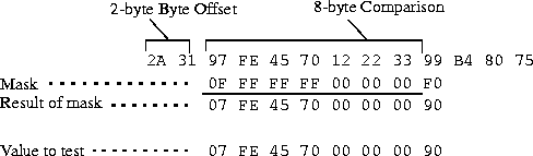
The packet matches this filter. Because the forward parameter is set to No, the packet will be dropped. The byte comparison works as follows:
admin> new filter out-only
FILTER/out-only read
admin> list input 1
valid-entry = no
forward = no
type = generic-filter
gen-filter = { 0 0 no no 00:00:00:00:00:00:00:00:00:00:00:00 00:00:00:0+
ip-filter = { 0 0.0.0.0 0.0.0.0 0.0.0.0 0.0.0.0 none 0 none 0 no }
admin> set valid = yesIn the Output-Filter rule that follows, the default values again match all packets, but the forwarding action is set to Yes. So the filter does not prevent outbound packets from resetting the timer or placing a call.
admin> list .. .. output 1
valid-entry = no
forward = no
type = generic-filter
gen-filter = { 0 0 no no 00:00:00:00:00:00:00:00:00:00:00:00 00:00:00:0+
ip-filter = { 0 0.0.0.0 0.0.0.0 0.0.0.0 0.0.0.0 none 0 none 0 no }
admin> set valid = yes
admin> set forward = yes
admin> write
FILTER/out-only written
Defining IP filters
The IP-Filter subprofile contains the following parameters, which are shown with their default values:
FILTER filter-name
      filter-name* = filter-name
      input-filters
            input-filters[1]-input-filters[12]
                  valid-entry = no
                  forward = no
                  type = ip-filter
                  ip-filter
                        protocol = 0
                        source-address-mask = 0.0.0.0
                        source-address = 0.0.0.0
                        dest-address-mask = 0.0.0.0
                        dest-address = 0.0.0.0
                        Src-Port-Cmp = none
                        source-port = 0
                        Dst-Port-Cmp = none
                        dest-port = 0
                        tcp-estab = no
      output-filters
            output-filters[1]-output-filters[12]
                  valid-entry = no
                  forward = no
                  type = ip-filter
                  ip-filter
                        protocol = 0
                        source-address-mask = 0.0.0.0
                        source-address = 0.0.0.0
                        dest-address-mask = 0.0.0.0
                        dest-address = 0.0.0.0
                        Src-Port-Cmp = none
                        source-port = 0
                        Dst-Port-Cmp = none
                        dest-port = 0
                        tcp-estab = no
If you specify a Source-Address-Mask, the MAX TNT applies it to the Source-Address value before comparing that value to the source address in a packet. The MAX TNT translates both the Source-Address-Mask and Source-Address values into binary format and then uses a logical AND to apply the Source-Address-Mask to the Source-Address. The mask hides the portion of the Source-Address that appears behind each binary 0 (zero) in the mask. A mask of all zeros (the default) masks all bits. If the Source-Address value is also all zeros, all source addresses in packets are matched. A mask of all ones (255.255.255.255) masks no bits, so the full source address for a single host is matched.
You can use the address mask to mask out the host portion of an address, for example, or the host and subnet portion, so the rule matches the source address from any host on a given network.
If you specify a Dest-Address-Mask, the MAX TNT applies it to the Dest-Address value before comparing that value to the destination address in a packet. The MAX TNT translates both the Dest-Address-Mask and Dest-Address values into binary format and then uses a logical AND to apply the Dest-Address-Mask to the Dest-Address. The mask hides the portion of the Dest-Address that appears behind each binary 0 (zero) in the mask. A mask of all zeros (the default) masks all bits. If the Dest-Address value is also all zeros, all destination addresses in packets are matched. A mask of all ones (255.255.255.255) masks no bits, so the full destination address for a single host is matched.
You can use the address mask to mask out the host portion of an address, for example, or the host and subnet portion, so the rule matches the destination address from any host on a given network.
A port number of zero matches nothing. The Src-Port-Cmp and Dst-Port-Cmp parameters specify how the source and destination port numbers, respectively, will be compared to packet contents. If set to None, no comparison is made. You can specify that the filter matches the packet if the packet's port number is Less (less than), Eql (equal to), Gtr (greater than), or Neq (not equal to) the port number specified in the filter.
Filtering only established TCP sessions
Tcp-Estab can be used to restrict the filter to packets in an established TCP session. You can use it only if the protocol number has been set to 6 (TCP). Example of an IP filter to prevent IP address spoofing
IP-address spoofing occurs when a remote device illegally acquires a local address and uses it to try to break through a Firewall or data filter. This section presents an example of a data filter that prevents IP-address spoofing. The filter first defines two Input-Filters that drop packets whose source address is on the local IP network or is the loopback address (127.0.0.0). In effect, these rules say: "If you see an inbound packet with one of these source addresses, drop the packet." The third Input-Filter accepts all remaining source addresses (by specifying a source address of 0.0.0.0) and forwards them to the local network.
The following procedure defines the filter:
admin> new filter ip-spoof
FILTER/ip-spoof read
admin> list input 1
valid-entry = no
forward = no
type = generic-filter
gen-filter = { 0 0 no no 00:00:00:00:00:00:00:00:00:00:00:00 00:00:00:+
ip-filter = { 0 0.0.0.0 0.0.0.0 0.0.0.0 0.0.0.0 none 0 none 0 no }
admin> set valid = yes
admin> set type = ip-filter
admin> list ip-filter
protocol = 0
source-address-mask = 0.0.0.0
source-address = 0.0.0.0
dest-address-mask = 0.0.0.0
dest-address = 0.0.0.0
Src-Port-Cmp = none
source-port = 0
Dst-Port-Cmp = none
dest-port = 0
tcp-estab = no
admin> set source-address-mask = 255.255.255.192
admin> set source-address = 192.100.50.128
admin> list .. .. 2
valid-entry = no
forward = no
type = generic-filter
gen-filter = { 0 0 no no 00:00:00:00:00:00:00:00:00:00:00:00 00:00:00:0+
ip-filter = { 0 0.0.0.0 0.0.0.0 0.0.0.0 0.0.0.0 none 0 none 0 no }
admin> set valid = yes
admin> set type = ip-filter
admin> list ip-filter
protocol = 0
source-address-mask = 0.0.0.0
source-address = 0.0.0.0
dest-address-mask = 0.0.0.0
dest-address = 0.0.0.0
Src-Port-Cmp = none
source-port = 0
Dst-Port-Cmp = none
dest-port = 0
tcp-estab = no
admin> set source-address-mask = 255.0.0.0
admin> set source-address = 127.0.0.0
admin> list .. .. 3
valid-entry = no
forward = no
type = generic-filter
gen-filter = { 0 0 no no 00:00:00:00:00:00:00:00:00:00:00:00 00:00:00:0+
ip-filter = { 0 0.0.0.0 0.0.0.0 0.0.0.0 0.0.0.0 none 0 none 0 no }
admin> set valid = yes
admin> set forward = yes
admin> set type = ip-filter
admin> list .. .. .. output 1
valid-entry = no
forward = no
type = generic-filter
gen-filter = { 0 0 no no 00:00:00:00:00:00:00:00:00:00:00:00 00:00:00:0+
ip-filter = { 0 0.0.0.0 0.0.0.0 0.0.0.0 0.0.0.0 none 0 none 0 no }
admin> set valid = yes
admin> set forward = yes
admin> set type = ip-filter
admin> list ip-filter
protocol = 0
source-address-mask = 0.0.0.0
source-address = 0.0.0.0
dest-address-mask = 0.0.0.0
dest-address = 0.0.0.0
Src-Port-Cmp = none
source-port = 0
Dst-Port-Cmp = none
dest-port = 0
tcp-estab = no
admin> set source-address-mask = 255.255.255.192
admin> set source-address = 192.100.50.128
admin> write
filter/ip-spoof written
In this example, the local network supports a Web server, and the administrator needs to carry out the following tasks:
The following procedure defines the filter:
admin> new filter web-safe
FILTER/web-safe read
admin> list input 1
valid-entry = no
forward = no
type = generic-filter
gen-filter = { 0 0 no no 00:00:00:00:00:00:00:00:00:00:00:00 00:00:00:0+
ip-filter = { 0 0.0.0.0 0.0.0.0 0.0.0.0 0.0.0.0 none 0 none 0 no }
admin> set valid = yes
admin> set forward = yes
admin> set type = ip-filter
admin> list ip-filter
protocol = 0
source-address-mask = 0.0.0.0
source-address = 0.0.0.0
dest-address-mask = 0.0.0.0
dest-address = 0.0.0.0
Src-Port-Cmp = none
source-port = 0
Dst-Port-Cmp = none
dest-port = 0
tcp-estab = no
admin> set protocol = 6
admin> set dest-address-mask = 255.255.255.255
admin> set dest-address = 192.9.250.5
admin> set dst-port-cmp = eql
admin> set dest-port = 80
admin> list .. .. 2
valid-entry = no
forward = no
type = generic-filter
gen-filter = { 0 0 no no 00:00:00:00:00:00:00:00:00:00:00:00 00:00:00:+
ip-filter = { 0 0.0.0.0 0.0.0.0 0.0.0.0 0.0.0.0 none 0 none 0 no }
admin> set valid = yes
admin> set forward = yes
admin> set type = ip-filter
admin> list ip-filter
protocol = 0
source-address-mask = 0.0.0.0
source-address = 0.0.0.0
dest-address-mask = 0.0.0.0
dest-address = 0.0.0.0
Src-Port-Cmp = none
source-port = 0
Dst-Port-Cmp = none
dest-port = 0
tcp-estab = no
admin> set protocol = 6
admin> set dst-port-cmp = gtr
admin> set dest-port = 1023
admin> list .. .. 3
valid-entry = no
forward = no
type = generic-filter
gen-filter = { 0 0 no no 00:00:00:00:00:00:00:00:00:00:00:00 00:00:00:+
ip-filter = { 0 0.0.0.0 0.0.0.0 0.0.0.0 0.0.0.0 none 0 none 0 no }
admin> set valid = yes
admin> set forward = yes
admin> set type = ip-filter
admin> list ip-filter
protocol = 0
source-address-mask = 0.0.0.0
source-address = 0.0.0.0
dest-address-mask = 0.0.0.0
dest-address = 0.0.0.0
Src-Port-Cmp = none
source-port = 0
Dst-Port-Cmp = none
dest-port = 0
tcp-estab = no
admin> set protocol = 17
admin> set dst-port-cmp = gtr
admin> set dest-port = 1023
admin> list .. .. 4
valid-entry = no
forward = no
type = generic-filter
gen-filter = { 0 0 no no 00:00:00:00:00:00:00:00:00:00:00:00 00:00:00:+
ip-filter = { 0 0.0.0.0 0.0.0.0 0.0.0.0 0.0.0.0 none 0 none 0 no }
admin> set valid = yes
admin> set forward = yes
admin> set type = ip-filter
admin> write
FILTER/web-safe written
Defining IPX filters
The IPX-Filter subprofile contains the following parameters, which are shown with their default values:
FILTER filter-name
      filter-name* = filter-name
      input-filters
            input-filters[1]-input-filters[12]
                  valid-entry = no
                  forward = no
                  type = ipx-filter
                  ipx-filter
                        src-net-address = 00:00:00:00
                        dest-net-address = 00:00:00:00
                        src-node-address = 00:00:00:00:00:00
                        dest-node-address = 00:00:00:00:00:00
                        src-socket = 00:00
                        src-socket-cmp = none
                        dest-socket = 0
                        dst-socket-cmp = none
      output-filters
            output-filters[1]-output-filters[12]
                  valid-entry = no
                  forward = no
                  type = ipx-filter
                  ipx-filter
                        src-net-address = 00:00:00:00
                        dest-net-address = 00:00:00:00
                        src-node-address = 00:00:00:00:00:00
                        dest-node-address = 00:00:00:00:00:00
                        src-socket = 00:00
                        src-socket-cmp = none
                        dest-socket = 0
                        dst-socket-cmp = none
<network-number>:<node-number>The Src-Net-Address and Dest-Net-Address parameters specify the network-number portion of the address. The network number is a unique 8-byte hexadecimal number that is common to all hosts on a particular LAN. NetWare servers have an internal network number that is the destination network address for file read/write requests. (If you are not familiar with internal network numbers, see your NetWare documentation for details.)
The Src-Node-Address and Dest-Node-Address parameters specify the node-number portion of the address. The node number is a 12-byte hexadecimal number that is unique to each node on a LAN. Each filter that specifies an IPX network number should also specify the corresponding node number. (For example, if you specify the Src-Net-Address in a filter, you should also specify the Src-Node-Address.)
Typically, a NetWare server address has the node number 1 (00:00:00:00:00:01) on the server's internal network. A node number of all 1s (FF:FF:FF:FF:FF:FF) matches all nodes on a LAN.
When you specify a NetWare socket number, you must also indicate how to compare the socket number in a packet to the specification in the filter. The Src-Socket-Cmp parameter specifies the method of comparison for the source socket number. You can specify that the filter matches the packet if the packet's source socket number is Less (less than), Eql (equal to), Gtr (greater than), or Neq (not equal to) the source socket number specified in the filter.
The Dst-Socket-Cmp parameter specifies the method of comparison for the destination socket number. You can specify that the filter matches the packet if the packet's destination socket number is Less (less than), Eql (equal to), Gtr (greater than), or Neq (not equal to) the destination socket number specified in the filter.
admin> new filter dstipx
FILTER/dstipx read
admin> list output 1
valid-entry = no
forward = no
Type = generic-filter
gen-filter = { 0 0 no no 00:00:00:00:00:00:00:00:00:00:00:00 00:00:00:+
ip-filter = { 0 0.0.0.0 0.0.0.0 0.0.0.0 0.0.0.0 none 0 none 0 no }
route-filter = { 0.0.0.0 0.0.0.0 0.0.0.0 0.0.0.0 0 none }
ipx-filter = { 00:00:00:00 00:00:00:00 00:00:00:00:00:00 00:00:00:00:0+
admin> set type = ipx-filter
admin> set ipx dest-net-address = 00003823
admin> set ipx dest-node-address = ffffffffffff
admin> list .. 2
valid-entry = no
forward = no
Type = generic-filter
gen-filter = { 0 0 no no 00:00:00:00:00:00:00:00:00:00:00:00 00:00:00:+
ip-filter = { 0 0.0.0.0 0.0.0.0 0.0.0.0 0.0.0.0 none 0 none 0 no }
route-filter = { 0.0.0.0 0.0.0.0 0.0.0.0 0.0.0.0 0 none }
ipx-filter = { 00:00:00:00 00:00:00:00 00:00:00:00:00:00 00:00:00:00:0+
admin> set forward = yes
admin> write
FILTER/dstipx read
admin> new filter srcipx
FILTER/srcipx read
admin> list input 1
valid-entry = no
forward = no
Type = generic-filter
gen-filter = { 0 0 no no 00:00:00:00:00:00:00:00:00:00:00:00 00:00:00:+
ip-filter = { 0 0.0.0.0 0.0.0.0 0.0.0.0 0.0.0.0 none 0 none 0 no }
route-filter = { 0.0.0.0 0.0.0.0 0.0.0.0 0.0.0.0 0 none }
ipx-filter = { 00:00:00:00 00:00:00:00 00:00:00:00:00:00 00:00:00:00:0+
admin> set type = ipx-filter
admin> set ipx src-net = 00000005
admin> set ipx src-node = 00abcde12345
admin> set ipx src-socket = 4002
admin> set ipx src-socket-cmp = eql
admin> list .. 2
valid-entry = no
forward = no
Type = generic-filter
gen-filter = { 0 0 no no 00:00:00:00:00:00:00:00:00:00:00:00 00:00:00:+
ip-filter = { 0 0.0.0.0 0.0.0.0 0.0.0.0 0.0.0.0 none 0 none 0 no }
route-filter = { 0.0.0.0 0.0.0.0 0.0.0.0 0.0.0.0 0 none }
ipx-filter = { 00:00:00:00 00:00:00:00 00:00:00:00:00:00 00:00:00:00:0+
admin> set forward = yes
admin> write
FILTER/srcipx read
Defining route filters
The Route-Filter subprofile contains the following parameters, which are shown with their default values:
FILTER filter-name
      filter-name* = ""
      input-filters
            input-filters[1]-input-filters[12]
                  valid-entry = no
                  forward = no
                  type = route-filter
                  route-filter
                        source-address-mask = 0.0.0.0
                        source-address = 0.0.0.0
                        route-mask = 0.0.0.0
                        route-address = 0.0.0.0
                        add-metric = 0
                        action = none
      output-filters
            output-filters[1]-output-filters[12]
                  valid-entry = no
                  forward = no
                  type = route-filter
                  route-filter
                        source-address-mask = 0.0.0.0
                        source-address = 0.0.0.0
                        route-mask = 0.0.0.0
                        route-address = 0.0.0.0
                        add-metric = 0
                        action = none
Route filter rules
Route filter rules affect only RIP packets. The following subsections provide background information about how the route filter parameters work. (For details, see the MAX TNT Reference Guide.) Source address and address mask
The Source-Address-Mask and Source-Address parameters specify the source of the route. These parameters have meaning only in input filters. A source address of zero with a mask of zero matches any source. Route address and mask
Route-Mask and Route-Address specify the destination of the route. When a route in a RIP packet matches this specification, the MAX TNT takes the specified action. Specifying the action to take
The Action parameter specifies what action to take on a route that matches the specified Route-Mask and Route-Address. These are the possible actions:
admin> new filter route-test
FILTER/route-test read
admin> list input 1
valid-entry = no
forward = no
type = generic-filter
gen-filter = { 0 0 no no 00:00:00:00:00:00:00:00:00:00:00:00 00:00:00:0+
ip-filter = { 0 0.0.0.0 0.0.0.0 0.0.0.0 0.0.0.0 none 0 none 0 no }
route-filter = { 0.0.0.0 0.0.0.0 255.0.0.0 90.0.0.0 0 deny }
admin> set valid = yes
admin> set type = route-filter
admin> list route
source-address-mask = 0.0.0.0
source-address = 0.0.0.0
route-mask = 255.0.0.0
route-address = 90.0.0.0
add-metric = 0
action = none
admin> set route-mask = 255.0.0.0
admin> set route-address = 90.0.0.0
admin> set action = deny
admin> list .. .. 2
admin> set valid = yes
admin> set type = route-filter
admin> set route action = accept
admin> write
FILTER/route-test written
Example of a filter that configures a route's metric
In the following example, an Output-Filter identifies the route 11.0.0.0 in outbound RIP packets and assigns a high metric to that route. Following are the commands entered and the system's responses:
admin> new filter metrics
FILTER/metrics read
admin> list output 1
valid-entry = no
forward = no
type = generic-filter
gen-filter = { 0 0 no no 00:00:00:00:00:00:00:00:00:00:00:00 00:00:00:0+
ip-filter = { 0 0.0.0.0 0.0.0.0 0.0.0.0 0.0.0.0 none 0 none 0 no }
route-filter = { 0.0.0.0 0.0.0.0 255.0.0.0 90.0.0.0 0 deny }
admin> set valid = yes
admin> set type = route-filter
admin> list route
source-address-mask = 0.0.0.0
source-address = 0.0.0.0
route-mask = 255.0.0.0
route-address = 90.0.0.0
add-metric = 0
action = none
admin> set route-mask = 255.0.0.0
admin> set route-address = 11.0.0.0
admin> set add-metric = 7
admin> set action = add
admin> write
FILTER/metrics written
Applying a filter to an interface
When you apply a filter to an interface, it causes the MAX TNT to examine packets on the interface. Following are the parameters related to applying a filter, shown with their default settings:
ANSWER-DEFAULTS
      session-info
            call-filter = ""
            data-filter = ""
            filter-persistence = no
CONNECTION station
      session-options
            call-filter = ""
            data-filter = ""
            filter-persistence = no
      ip-options
            route-filter = ""
ETHERNET {shelf-N slot-N N }
      filter-name= ""
IP-INTERFACE { {shelf-N slot-N N } N}
      route-filter = ""
For information about each parameter, see the MAX TNT Reference Guide. For information about the effect of applying a data filter, call filter, or route filter, see What filters are for.
How the system uses Answer-Defaults profile settings
If the MAX TNT uses a local Connection profile for authentication, it does not use filters applied in the Answer-Defaults Session-Info subprofile. How filter persistence affects filters
Filter persistence is needed to allow Secure Access Firewalls to persist across connection state changes, but it is not needed for filters. If you do set it for a filter, the filter persists across connection state changes. For more information about persistence, see Appendix C, Secure Access Firewalls.
Applying a data filter to a WAN or LAN interface
When you apply a filter to a WAN interface, it takes effect when the connection is brought up. If both a data filter and call filter are applied, the data filter is applied first, so only those packets that pass the data filter reach the call filter.
admin> read conn tlynch
CONNECTION/tlynch read
admin> list session
call-filter = ""
data-filter = ""
filter-persistence = no
idle-timer = 120
ts-idle-mode = no-idle
ts-idle-timer = 120
admin> set data-filter = ip-spoof
admin> writeEthernet interfaces are connected routes, so call filters are not applicable. However, you can apply a data filter that affects which packets are allowed to reach the Ethernet or leave the Ethernet for another interface. A filter applied to an Ethernet interface takes effect immediately. If you change the Filter profile definition, the changes apply as soon as you save the Filter profile.
CONNECTION/tlynch written
Following is an example of a procedure that applies a filter to a local network interface:
admin> dir ether
     8  12/11/1996 15:58:08  { shelf-1 controller 1 }
    16  12/18/1996 16:17:17  { shelf-1 Slot-12 1 }
    16  12/18/1996 16:17:17  { shelf-1 Slot-12 2 }
    16  12/18/1996 16:17:17  { shelf-1 Slot-12 3 }
    16  12/18/1996 16:17:17  { shelf-1 Slot-12 4 }

admin> read ether {1 12 1}
ETHERNET/{ shelf-1 Slot-12 1 } read
admin> list
interface-address* = { shelf-1 slot-12 1 }
mac-address = 00:c0:7b:69:94:38
ether-if-type = utp
filter-name = ""
admin> set filter-name = web-safe
admin> write
ETHERNET/{ shelf-1 Slot-12 1 } written
admin> read conn bob
CONNECTION/bob read
admin> list session
call-filter = ""
data-filter = ""
filter-persistence = no
idle-timer = 120
ts-idle-mode = no-idle
ts-idle-timer = 120
admin> set call-filter = out-only
admin> set idle-timer = 20
admin> write
CONNECTION/bob written
admin> read conn bdv
CONNECTION/bdv read
admin> set ip-options route-filter = route-test
admin> writeFollowing is an example of applying a route filter named Route-Test to a local network interface:
CONNECTION/bdv written
admin> read ip-interface { { 1 c 1 } 0 }
IP-INTERFACE/{ { shelf-1 controller 1 } 0 } read
admin> set route-filter = route-test
admin> write
IP-INTERFACE/{ { shelf-1 controller 1 } 0 } written
Copyright © 1998, Ascend Communications, Inc. All rights reserved.