[Top][Contents][Prev][Next][Last]Search


Installing the MAX TNT Chassis


This chapter covers the following topics:
Installation overview
Before you begin
Power requirements
Checking the package contents
Understanding the back panel
Understanding the shelf-controller backpanel
Verifying the rotary switch setting and PCMCIA card
Rack mounting the MAX TNT
Installing a slot card
Connecting the MAX TNT to the LAN
Connecting a workstation to the serial port
Powering on the MAX TNT
Where to go next

Installation overview

This chapter explains how to install a single shelf MAX TNT. If you are installing a multishelf system, read this chapter and Chapter 3, "Performing Basic Configuration," before installing your system.

Table 2-1 lists the sections describing installation tasks you might need to perform, and provides a brief description of each.

Table 2-1. MAX TNT installation overview

Task

Description

Before you begin

Explains what you need before installing the MAX TNT.

Power requirements

Explains the MAX TNT power requirements.

Checking the package contents

Helps you verify that you have all the necessary hardware.

Understanding the back panel

Describes the elements of the MAX TNT back panel.

Understanding the shelf-controller backpanel

Describes the MAX TNT shelf controller, which controls the slot cards and contains lights that indicate overall system status.

Verifying the rotary switch setting and PCMCIA card

Describes the multishelf rotary switch and the PCMCIA card. The PCMCIA card must be installed for the MAX TNT to boot.

Rack mounting the MAX TNT

Describes how to install the MAX TNT in a rack.

Installing a slot card

Explains how to install an slot card into the MAX TNT chassis.

Connecting the MAX TNT to the LAN

Explains how to connect the MAX TNT shelf-controller Ethernet port to the LAN.

Connecting a workstation to the serial port

Explains how to connect a PC to MAX TNT serial port to perform first time configuration. After assigning an IP address and gateway to the MAX TNT, you can configure it remotely through Telnet.

Powering on the MAX TNT

Explains how to power on the MAX TNT and check the PCMCIA card file system to diagnose potential problems with booting up.

Where to go next

Explains where to go after installing the MAX TNT chassis.

Before you begin

Before you install the MAX TNT, make sure you have the following:

Power requirements

The MAX TNT allows you to freely mix and match the various types of expansion cards with few restrictions. Here is information to help determine power requirements:

Checking the package contents

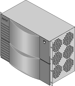
The MAX TNT package contents vary, depending on the base unit and slot cards you order. The first step after opening the package is to verify that you have the system you ordered. Figure 2-1 shows a standalone MAX TNT shelf. A multishelf system combines multiple interleaved shelves in a chassis.

Figure 2-1. Standalone shelf front panel

Verify that the package also contains the following items:

If you are missing any items, contact your MAX TNT distributor.

Understanding the back panel

Figure 2-2 shows the back panel of a standalone shelf. The shelf controller is always slot 17. The remaining slots are numbered 1 through 16. (For information about a installing a slot card in a slot, see the chapter about the card, later in this manual.)

Figure 2-2. Back panel of the MAX TNT

Understanding the shelf-controller backpanel

Before you begin installing the hardware, you need some understanding of the ports and other items on the MAX TNT shelf controller. Refer to Figure 2-3 and Table 2-2 for the location and function of each element on the shelf controller.

Figure 2-3. MAX TNT shelf-controller backpanel

Table 2-2. Description of shelf-controller backpanel items

Backpanel item

Description

Uplink/Downlink

Ports for intershelf communications.

UTP port

Ethernet port to connect Unshielded Twisted-Pair (UTP) Ethernet LAN cable to the MAX TNT.

Serial port

Ethernet port to connect Shielded Twisted-Pair (STP) Ethernet LAN cable to the MAX TNT.

PCMCIA slots

Two flash PCMCIA slots, labeled 1 and 2.

DRAM upgrade slot

PCMCIA slot for DRAM upgrades.

Shelf-Select rotary switch

This switch is used for MAX TNT multishelf configurations. Each shelf in a multishelf system must have its rotary switch set to a unique number. (See Chapter 4, "Installing a Multishelf System," for information about configuring a multishelf system.)

The lights on the shelf-controller back panel

The lights (also called LEDs) on the MAX TNT back panel can be helpful if you experience a problem, especially if it occurs shortly after power on. Figure 2-4 shows the location of the lights on the back panel, and Table 2-3 describes them.

Figure 2-4. Location of the MAX TNT lights

Table 2-3. MAX TNT lights

Lights

Description

1

Green. On when the unit has power.

2

Green. On for any functioning shelf in a multishelf system, whether it is configured as master or slave.

3

Yellow. Behaves as follows:

  • On after you reset the unit

  • Off after the unit passes Power-On Self Test (POST) and is running

  • Blinks if a fatal error has occurred

4

Yellow. This is the multishelf alarm light. If the master shelf goes down (if, for example, the multishelf cable is removed), this light goes on, on each slave shelf, after about nine seconds. Note that on the master shelf, this alarm light does not go on.

5

Green. On when Power Supply A is installed and working.

6

Green. On when Power Supply B is installed and working.

7

Yellow. On when Power Supply A is installed and a fault occurs.

8

Yellow. On when Power Supply B is installed and a fault occurs.

9

Green. On when an Ethernet 10Base-T link has been established.

10

Green. On when an Ethernet AUI link has been established.

11

Green. On when the Ethernet link is active.

12

Green. On when the Ethernet link is active and link integrity has been confirmed.

13

Green. On when there is Ethernet activity between MAX TNT shelves.

14

Yellow. On when an Ethernet collision occurs.

Verifying the rotary switch setting and PCMCIA card

Make sure the switch is not set to 0. Figure 2-5 shows an acceptable setting. (In a multishelf system, each shelf must have a unique setting.)

Caution: If the rotary switch is set to 0, the MAX TNT will not operate correctly.
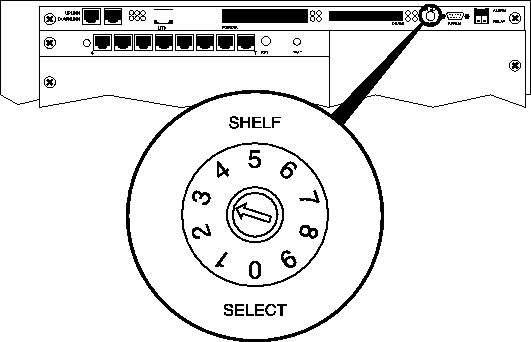
Figure 2-5. Verifying the rotary switch setting

Also, make sure the PCMCIA card is inserted in the first PCMCIA slot.

Caution: Do not remove the PCMCIA flash card while the MAX TNT is running. Doing so can damage the card and require its replacement.

Rack mounting the MAX TNT

Before installing the MAX TNT in a rack, you must install the MAX TNT rack ears as illustrated in Figure 2-6. These rack ears should come with your unit. If you do not receive them, contact your Ascend reseller. Apply 7 to 8 in/lbs of torque to each screw.

Figure 2-6. Installing the MAX TNT rack ears

You can mount the MAX TNT in either a 19- or 23-inch rack. A single MAX TNT shelf has the dimensions shown in Figure 2-7.

Figure 2-7. MAX TNT dimensions

Insert the unit in the rack and secure it as shown in Figure 2-8. If you need more information, refer to the instructions that came with your rack.

You need not concern yourself with air gaps between MAX TNT shelves on a rack, because the MAX TNT fans sufficiently cool each shelf.

Figure 2-8. Mounting the MAX TNT in a rack

Installing a slot card

If your MAX TNT package includes slot cards that are not already installed in your MAX TNT, insert the cards now. Proceed as follows:
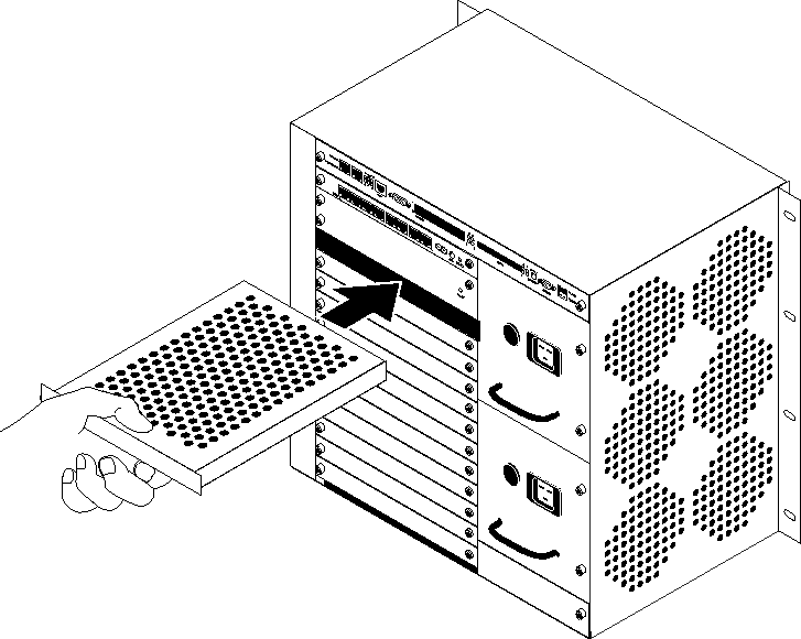
  1. Hold the slot card with the panel facing you and the lock screw on the left, and insert the card into the open slot as shown in Figure 2-9.

Figure 2-9. Inserting a slot card into a MAX TNT

  1. Push the card along the internal card guides until jackscrew on the right side of the card panel is seated in the hole in the MAX TNT backpanel. The panel of the slot card should touch the back panel of the MAX TNT.

Caution: Do not force the slot card into the slot. Doing so can damage the card or slot connector.

  • Tighten the lock screw on the left side of the card, as shown in Figure 2-10.

    All MAX TNT slot cards are hot-swappable, meaning that you can safely insert or remove cards while the MAX TNT power is on.
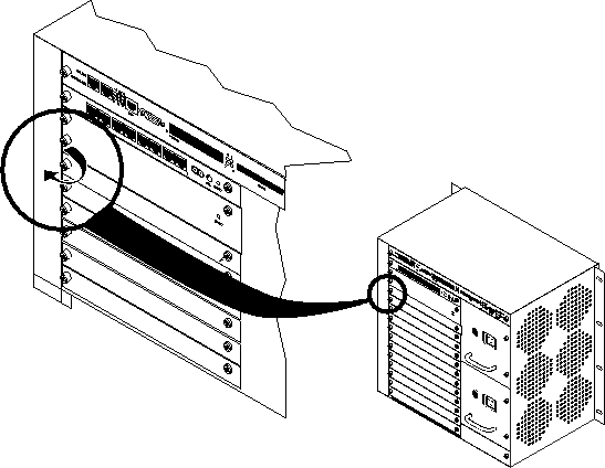
    Figure 2-10. Tightening slot card lock screws

    Connecting the MAX TNT to the LAN

    All MAX TNT systems have an Ethernet port on the shelf-controller. This Ethernet port is designed for out-of-band management and light traffic loads. It is not intended to be the primary Ethernet interface for the system. If your MAX TNT will be routing heavy Ethernet traffic use an Ethernet card.

    If do not need a LAN interface, skip this section and proceed to Connecting a workstation to the serial port.

    To connect the MAX TNT to your LAN, plug Ethernet LAN cables into one of the unit's Ethernet ports. Figure 2-11 shows the Ethernet LAN cable connected to the shelf controller Ethernet interface for out-of-band management.

    Figure 2-11. Connecting Ethernet cable

    Connecting a workstation to the serial port

    To perform the initial configuration of the MAX TNT, you must connect a cable to MAX TNT serial port.
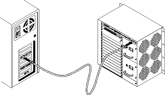
    1. Connect a serial cable from your workstation to the MAX TNT as shown in Figure 2-12.

    Figure 2-12. Connecting a serial cable to MAX TNT

    1. Set the terminal emulation package in your communications software as follows:

      • 9600 bps

      • Direct connection

      • 8 data bits

      • No parity

      • 1 stop bit

      • No flow control

    Powering on the MAX TNT

    To power on the MAX TNT:

    1. Position yourself so that you can watch the lights on the back panel while you view the monitor display.

    2. Turn on the power to the unit. After a few minutes, the terminal emulator should display the following messages (if it does not, press Ctrl-L to refresh the screen):

                        *** TNT, unconfigured unit***
        The system date is: Thu Aug 11 12:34:39 1997
        If incorrect, please enter the proper value using this command:
        date yymmddhhmm
        Please configure these profiles:
        SYSTEM
        IP-GLOBAL
        IP-INTERFACE
        LOG
        SERIAL
        for your operating environment.
        TNT>

    3. Check the PCMCIA flash-card file system to verify that there are no errors on the card or in its contents:

        admin>fsck 1
        ffs check in progress for card 1...
        Dir 1 not in use
        Dir 2 has magic, size 16, sequence 0x8
        Using dir entry: 2, total data blocks: 0x40, directory size: 16
        10-unchan-t1-card:(0x0b)
        reg good 408039 (0x0639e7) Jul 24 08:17
        8t1-card:(0x04)
        reg good 167564 (0x028e8c) Jul 24 08:16
        shelf-forward:(0x0f)
        reg good 371393 (0x05aac1) Jul 3 14:10
        t3-card:(0x0d)
        reg good 184904 (0x02d248) Jul 24 08:16
        unknown load type:(0x11)
        reg good 452363 (0x06e70b) Jul 7 11:59
        192hdlc-card:(0x07)
        reg good 458731 (0x06ffeb) Jul 24 08:16
        48modem-card:(0x06)
        reg good 472763 (0x0736bb) Jul 24 08:16
        4ether-card:(0x08)
        reg good 119951 (0x01d48f) Jul 24 08:16
        flash card 1 fsck: good.

    Where to go next

    To perform the initial configuration of the MAX TNT, see Chapter 3, "Performing Basic Configuration."


    [Top][Contents][Prev][Next][Last]Search

    techpubs@eng.ascend.com

    Copyright © 1997, Ascend Communications, Inc. All rights reserved.