
This chapter covers the following topics:
Introduction to OSPF
Open Shortest Path First (OSPF) is the next generation Internet routing protocol. The Open in its name refers to the fact that OSPF was developed in the public domain as an open specification. Shortest Path First refers to an algorithm developed by Dijkstra in 1978 for building a self-rooted shortest-path tree from which routing tables can be derived. (For a description of the algorithm, see The link-state routing algorithm.)
RIP limitations solved by OSPF
The rapid growth of the Internet has pushed Routing Information Protocol (RIP) beyond its capabilities, particularly in the areas of distance-vector metrics, the 15-hop limitation, and slow convergence due to excessive routing traffic. Distance-vector metrics
RIP is a distance-vector protocol, which uses a hop count to select the shortest route to a destination network. RIP always uses the lowest hop count, regardless of the speed or reliability of a link. 15-hop limitation
With RIP, a destination that requires more than 15 consecutive hops is considered unreachable, which inhibits the maximum size of a network. OSPF has no hop limitation-you can add as many routers to a network as you want. Excessive routing traffic and slow convergence
RIP creates a routing table and then propagates it throughout the internet of routers, hop by hop. The time it takes for all routers to receive information about a topology change is called convergence. A slow convergence can result in routing loops and errors.
Ascend implementation of OSPF
The primary goal of the OSPF implementation in this release is to allow the MAX TNT to communicate with other routers within a single Autonomous System (AS).
admin> dir ip-intOSPF can be enabled on any one of the port's IP interfaces, but not on more than one interface for the same port.
8 02/14/1998 14:43:14 { { shelf-1 slot-15 2 } 0 }
8 02/14/1998 14:43:14 { { shelf-1 slot-15 3 } 0 }
8 02/14/1998 14:43:14 { { shelf-1 slot-15 4 } 0 }
20 02/14/1998 14:57:48 { { shelf-1 controller 1 } 0 }
11 02/14/1998 15:24:28 { { shelf-1 slot-15 1 } 0 }
10 03/04/1998 11:56:47 { { shelf-1 slot-15 1 } 1 }
10 03/04/1998 11:57:01 { { shelf-1 slot-15 1 } 2 }
10 03/04/1998 11:57:09 { { shelf-1 slot-15 1 } 3 }
admin> ospf ?
OSPF usage:For information about using these commands, see the MAX TNT Reference Guide.
OSPF ? Display help information
OSPF areas Display OSPF areas
OSPF border-routers Display OSPF border router information
OSPF database Display OSPF link-state database
OSPF errors Display OSPF errors
OSPF general Display OSPF general info
OSPF interfaces Display OSPF interfaces
OSPF neighbor Display OSPF neighbors
OSPF rtab Display OSPF routing tab
OSPF timer-queue Display OSPF timer queue
OSPF stats Display OSPF stats
An Autonomous System (AS) is a group of OSPF routers exchanging information, typically under the control of one company. An AS can include a large number of networks, all of which are assigned the same AS number. All information exchanged within the AS is interior.
Exterior protocols are used to exchange routing information between Autonomous Systems. They are referred to by the acronym EGP (exterior gateway protocol). The AS number may be used by border routers to Filter out certain EGP routing information. OSPF can make use of EGP data generated by other border routers and added into the OSPF system as ASE information, as well as static routes configured locally or in RADIUS.
Support for variable length subnet masks
OSPF enables the flexible configuration of IP subnets. Each route distributed by OSPF has a destination and mask. Two different subnets of the same IP network number may have different sizes (different masks). This is commonly referred to as variable-length subnet masks (VLSM), or Classless Inter-Domain Routing (CIDR). A packet is routed to the best (longest or most specific) match. Host routes are considered to be subnets whose masks are all ones (0xFFFFFFFF).
Interior gateway protocol (IGP)
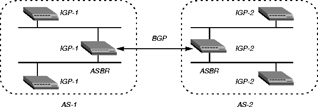
OSPF keeps all AS-internal routing information within the AS. All information exchanged within the AS is interior.
Figure 5-1. OSPF Autonomous System Boundary Routers (ASBRs)
Exchange of routing information
OSPF stores its information about the network in a topological database and propagates only changes to the database. Adjacency is a relationship formed between selected neighboring routers for the purpose of exchanging routing information. Not every pair of neighboring routers become adjacent. Routers connected by point-to-point networks and virtual links always become adjacent. On multi-access networks, all routers become adjacent to both the Designated Router and the Backup Designated Router. Designated and Backup Designated Routers
In OSPF terminology, a broadcast network is any network that has more than two OSPF routers attached and supports the capability to address a single physical message to all of the attached routers. 
Figure 5-2. OSPF Designated Router (DR) and Backup Designated Router (BDR)
To reduce the number of adjacencies each router must form, OSPF calls one of the routers the Designated Router. A Designated Router is elected as routers are forming adjacencies, and then all other routers establish adjacencies only with the Designated Router. This simplifies the routing table update procedure and reduces the number of link-state records in the database. The Designated Router plays other important roles as well to reduce the overhead of a OSPF link-state procedures. For example, other routers send LSAs to only the Designated Router by using the All-Designated-Routers multicast address of 224.0.0.6.
Configurable cost metrics
The administrator assigns a cost to the output side of each router interface. The lower the cost, the more likely the interface is to be used to forward data traffic. Costs can also be associated with the externally derived routing data.
Figure 5-3. OSPF costs for different types of links
Hierarchical routing (areas)
If a network is large, the size of the database, time required for route computation, and related network traffic become excessive. An administrator can partition an AS into areas to provide hierarchical routing, with a backbone area connecting the other areas. The backbone area is special and always has the area number 0.0.0.0. Other areas are assigned area numbers that are unique within the AS.
Figure 5-4. Dividing an OSPF Autonomous System (AS) into areas
Because the MAX TNT does not currently operate as an ABR, you should not configure it to route OSPF in a stub area if any of its links are AS-external.
For NSSAs, all routes imported to OSPF must have the P-bit set (P stands for propagate). When the MAX TNT is configured to route OSPF in an NSSA, all external routes that are imported to OSPF have the P-bit (P stands for propagate) enabled in their respective link-state entry. These external routes are considered Type-7 ASE LSAs. When the P-bit is enabled, Area Border Routers translate Type-7 LSAs to Type-5 LSAs, which can then be flooded to the backbone.
The external routes imported to OSPF may be routes defined in local Connection profiles or RADIUS profiles, or static routes defined in IP-Route profiles.
The link-state routing algorithm
Link-state routing algorithms require that all routers within a domain maintain synchronized (identical) topological databases, and that the databases describe the complete topology of the domain. An OSPF router's domain may be an AS or an area within an AS.
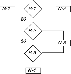
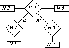
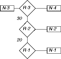
For example, for the network topology in Figure 5-5:
Figure 5-5. Sample OSPF topology
From the link-state database, each router builds a self-rooted shortest-path tree, and then calculates a routing table stating the shortest path to each destination in the AS. (The table also includes externally derived routing information.)

|
Destination
|
Next Hop
|
Metric
|
|
Network-1
|
Direct
|
0
| |
|
Network-2
|
Direct
|
0
| |
|
Network-3
|
Router-2
|
20
| |
|
Network-4
|
Router-2
|
50
| |
|
|
|
| |
|
|
|
|

|
Destination
|
Next Hop
|
Metric
|
|
Network-1
|
Router-1
|
20
| |
|
Network-2
|
Direct
|
0
| |
|
Network-3
|
Direct
|
0
| |
|
Network-4
|
Router-2
|
30
|

|
Destination
|
Next Hop
|
Metric
|
|
Network-1
|
Router-2
|
50
| |
|
Network-2
|
Router-2
|
30
| |
|
Network-3
|
Direct
|
0
| |
|
Network-4
|
Direct
|
0
| |
|
|
|
|
Configuring the OSPF router
This section describes how to configure the MAX TNT OSPF router in the IP-Global profile. It covers the following topics:
IP-GLOBALFor detailed information about each parameter, see the MAX TNT Reference Guide.
ospf-ase-pref = 150
rip-tag = c8:00:00:00
rip-ase-type = 1
IP-GLOBALIf you set the AS-Boundary-Router parameter to No, the MAX TNT does not perform ASBR calculations.
ospf-global
as-boundary-router = yes
Configuring LAN and WAN interfaces
This section describes how to add the MAX TNT to an OSPF network. It shows a local OSPF interface in a normal area, and one that routes OSPF across a WAN link. This section assumes that the MAX TNT is configured for IP, as described in Chapter 4, IP Routing.
Following are the related parameters, shown with their default values:
IP-INTERFACE { { shelf-N slot-N N } N }
      ospf-options
            active = no
            area = 0.0.0.0
            area-type = normal
            hello-interval = 10
            dead-interval = 40
            priority = 5
            authen-type = simple
            auth-key = ascend0
            cost = 1
            down-cost = 16777215
            ase-type = type-1
            ase-tag = c0:00:00:00
            transit-delay = 1
            retransmit-interval = 5
CONNECTION stationThe same parameters appear in the OSPF subprofiles of the IP-Interface and Connection profiles. For detailed information about each parameter, see the MAX TNT Reference Guide.
ip-options
ospf-options
active = no
area = 0.0.0.0
area-type = normal
hello-interval = 30
dead-interval = 120
priority = 5
authen-type = simple
auth-key = ascend0
cost = 10
down-cost = 1000
ase-type = type-1
ase-tag = c0:00:00:00
transit-delay = 1
retransmit-interval = 5
Example of a LAN OSPF interface
Figure 5-6 shows five OSPF routers in the backbone area of an AS. Because all OSPF routers are in the same area, the units form adjacencies and synchronize their databases. This example shows how to configure the LAN interface of the unit labeled MAX-TNT-2 in Figure 5-6.
Figure 5-6. OSPF on a LAN interface
Although there is no limitation stated in the RFC about the number of routers in the backbone area, you should keep the number of routers relatively small, because changes that occur in area zero are propagated throughout the AS. Another way to configure the same units would be to create a second area (such as 0.0.0.1) in one of the existing OSPF routers, and add the MAX TNT to that area. You can then assign the same area number (0.0.0.1) to all OSPF routers reached through the MAX TNT across a WAN link.
admin> read ip-int {{ 1 c 1 } 0 }
IP-INTERFACE/{ { shelf-1 controller 1 } 0 } read
admin> set ip-address = 10.168.8.17/24
admin> set rip-mode = routing-off
admin> set ignore-def-route = yesThe next set of commands configures the unit as an OSPF router in the backbone area:
admin> list ospf
active = no
area = 0.0.0.0
area-type = normal
hello-interval = 10
dead-interval = 40
priority = 5
authen-type = simple
auth-key = ascend0
cost = 1
down-cost = 16777215
ase-type = type-1
ase-tag = c0:00:00:00
transit-delay = 1
retransmit-delay = 5
admin> set active = yes
admin> write
IP-INTERFACE/{ { shelf-1 controller 1 } 0 } written
Example of WAN OSPF interfaces
This example shows how to configure Connection profiles in the MAX TNT units shown in Figure 5-7, to enable them to route OSPF across the WAN that separates them. In this example, the unit labeled MAX-TNT-2 has the IP address 10.2.3.4/24, and the unit labeled MAX-TNT-1 has the address 10.168.8.17/24.
Figure 5-7. OSPF on a WAN interface
admin> read conn maxtnt2ink
CONNECTION/maxtnt2link read
admin> set ip remote = 10.168.8.17/24
admin> set ip rip = routing-off
admin> set ip ospf active = yes
admin> writeFollowing is an example that configures the OSPF WAN link in the unit labeled MAX-TNT-2 in Figure 5-7:
CONNECTION/maxtnt2link written
admin> read conn maxtnt1link
CONNECTION/maxtnt1link read
admin> set ip remote = 10.2.3.4/24
admin> set ip rip = routing-off
admin> set ip ospf active = yes
admin> write
CONNECTION/maxtnt1link written
Figure 5-8. Including ASE routes in the OSPF environment
admin> read conn pipeline1
CONNECTION/pipeline1 read
admin> set ip remote = 10.6.7.168/24
admin> set ip rip = routing-off
admin> list ip ospf
active = no
area = 0.0.0.0
area-type = normal
stub-default-cost = 0
hello-interval = 30
dead-interval = 120
priority = 5
authen-type = simple
auth-key = ascend0
cost = 10
down-cost = 1000
ase-type = type-1
ase-tag = c0:00:00:00
transit-delay = 1
retransmit-delay = 5
admin> set active = no
admin> set cost = 240The next set of commands causes the MAX TNT to tag routes learned from RIP and to import them as Type-2 LSAs:
admin> set ase-type = type-2
admin> set ase-tag = cfff8000
admin> write
CONNECTION/pipeline1 written
IP-ROUTE name
      name* = external
      dest-address = 10.4.5.0/22
      gateway-address = 10.4.5.7
      metric = 0
      cost = 1
      preference = 100
      third-party = no
      ase-type = type-1
      ase-tag = c0:00:00:00
      private-route = yes
      active-route = yes
      ase7-adv = n/a
admin> read ip-int {{ 1 c 1 } 0 }
IP-INTERFACE/{ { shelf-1 controller 1 } 0 } read
admin> set ospf area-type = nssa
admin> write
IP-INTERFACE/{ { shelf-1 controller 1 } 0 } written
admin> read connection ase-like
CONNECTION/ase-link read
admin> set ip-options remote = 10.4.5.7/22
admin> set ip-options rip = routing-off
admin> set ip-options ospf active = yes
admin> write
CONNECTION/ase-link written
admin> new ip-route type7
IP-ROUTE/type7 read
admin> set dest = 10.4.5.0/22
admin> set gateway = 10.4.5.7
admin> write
IP-ROUTE/type7 written
IP-GLOBALWhen Pool-Summary is set to Yes and OSPF is enabled, OSPF looks at the Pool-OSPF-Adv-Type parameter to decide how to import pool addresses into OSPF. You can set the parameter to one of the following values:
pool-ospf-adv-type = type-1
Configuring OSPF information in static routes
When the MAX TNT starts up, it builds the initial routing table by using its known static routes, which include those defined in IP-Interface profiles, Connection profiles, and IP-Route profiles. In addition, whenever a route changes, the MAX TNT reads the static routes defined in IP-Route profiles. The following IP-Route parameters (shown with sample settings) apply only when OSPF is enabled:
IP-ROUTE nameFor information about the ASE-Type and ASE-Tag parameters, see Specifies the type of metric to apply to routes learned from RIP. Type-1 expresses the metric in the same units as the interface cost. Type-2 is considered larger than any link-state path. This applies in a Connection profile only when OSPF is not active..
cost =1
third-party = no
ase-type = type-1
ase-tag = c0:00:00:00
ase7-adv = n/a
Assigning a cost to a static route
The lower the cost assigned to a route, the more likely that the route will be used to forward traffic. Typically, you should account for the bandwidth of a connection when assigning costs. For example, the cost for a single-channel connection would be 24 times greater than for a T1 link.
admin> new ip-route 56klink
IP-ROUTE/56klink read
admin> set dest = 10.1.2.0/24
admin> set gateway = 10.9.8.10
admin> set cost = 25
admin> write
IP-ROUTE/56klink written
Depending on the topology of the network, it might be possible for other routers to use this type of third-party LSA to route directly to the forwarding address without involving the advertising router, thus increasing the total network throughput. This feature can be used only if all OSPF routers know how to route to the forwarding address. This usually means that the forwarding address is on a local network that has an OSPF router acting as the forwarding router, or that Designated Router is sending LSAs for that Ethernet to any area that sees the static route's forwarding address LSAs. Note that third-party routing cannot be used when ASE Type-7s are advertised (as specified in RFC 1587).
In the following sample route, the MAX TNT will advertise a third-party route (a forwarding address) for the destination 10.1.2.0. The forwarding address is 10.9.8.10.
admin> new ip-route third-party
IP-ROUTE/third-party read
admin> set dest = 10.1.2.0/24
admin> set gateway = 10.9.8.10
admin> set third-party = yes
admin> write
IP-ROUTE/third-party written
Copyright © 1998, Ascend Communications, Inc. All rights reserved.