![[Top]](../images/home.jpg)
![[Contents]](../images/contents.jpg)
![[Prev]](../images/previous.jpg)
![[Next]](../images/next.jpg)
![[Last]](../images/index.jpg)


Configuring RADSL Cards
This chapter covers the following topics:
For information about installing the RADSL voice splitter, see Appendix B, "Configuring the RADSL Voice Splitter. "
Introduction
Note: The MAX TNT must have software version 1.3Ai2 or later to support ADSL. Refer to
the MAX TNT release notes for information about obtaining and loading MAX TNT software.
Rate Adaptive Digital Subscriber Line (RADSL) Carrierless Amplitude Phase (CAP) is part of a broad range of Ascend MultiDSL offerings that let you implement DSL technologies immediately. RADSL supports high-bandwidth applications such as remote access, Internet or intranet access and telecommuting. RADSL supports the following asymmetric transfer rates:
Rate Adaptive Digital Subscriber Line (RADSL)
RADSL allows the MAX TNT to detect the noise level on the line and automatically adjust the data transfer rate for optimum performance.
Installing the RADSL card
The RADSL card is illustrated in Figure 14-1.

Figure 14-1. MAX TNT RADSL card
You install RADSL cards in the same way you install other MAX TNT slot cards. For instructions, see Installing a slot card.
Configuring the maximum downstream rate
The Max-Down-Stream-Rate parameter specifies the maximum down-stream rates the transceiver supports.
If loop quality is poor, the transceiver chooses the lower rates, and good loop quality causes the transceiver to choose the higher rates. If the loop quality is very poor, the transceiver will not train at all, and will be unable to connect to the remote side. In that case, the administrator must specify a lower maximum down-stream rate, because the transceiver does not cross rate boundaries.
For example, if the transceiver is configured for 7160000bps and the loop quality is so poor that the transceiver will not connect to the remote side, the transceiver does not automatically adjust the down-rate into the 5120000bps range. The administrator needs to configure the Max-Down-Stream-Rate to the lower rate.
Note: You can set the maximum down-stream rate with SNMP by writing the DownRate
object in the AdslCapLineStatusEntry MIB.
Sample RADSL configuration
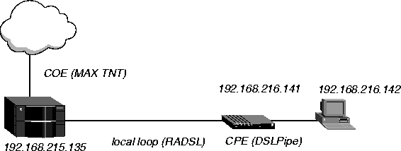
In Figure 14-2, a DSLPipe connects to a MAX TNT RADSL card. This connection provides data transfer rates of up to 7.168 Mbps downstream and 1.088 Mbps upstream over a single pair of copper wires using Frame Relay as the transport protocol.

Figure 14-2. Sample RADSL setup
Configuring an RADSL connection requires the following general steps:
Configuring the ADSL profile
To configure the ADSL profile:
- Read in the ADSL profile. For example, if the RADSL card is installed in slot 11 of shelf
1 and the remote DSLPipe is connected to port 1:
admin> read adsl-cap {1 11 1}
- List the profile:
admin> list
- Enable the port:
admin> set enabled=yes
- List the contents of the Line-Config profile:
admin> list line-config
- Assign this port to a nailed group:
admin> set nailed-group=1
This nailed group points to the Frame Relay profile you will create later. The nailed group must be unique for each active WAN interface.
- If required, set the maximum down stream rate:
admin> set max-down-stream-rate = 5120000
- Move up to the top-level profile:
admin> list..
- Write the profile:
admin> write
Configuring the Connection profile
To configure the Connection profile:
- Create a new Connection profile:
admin> new con coe-11-1
- List the profile:
admin> list
- Enable the profile:
admin> set active=yes
- Set the encapsulation type to Frame Relay:
admin> set encapsulation-protocol=frame relay
- List the IP options submenu:
admin> list ip-options
- Set the IP address of the DSLPipe connecting to the MAX TNT:
admin> set remote-address=192.168.216.141/24
- Set the IP address of the MAX TNT RADSL port.
admin> set local-address=192.168.215.135/24
- Move up to the higher-level profile:
admin> list..
- List the Frame Relay options submenu:
admin> list fr-options
- Link this Connection profile to the Frame Relay profile you will create in the next section:
admin> set frame-relay-profile=fr-prof-1
- Set the DLCI to the same value as the DSLPipe:
admin> set dlci=16
- Write the profile:
admin> write
Configuring the Frame Relay profile
To configure the Frame Relay profile:
- Create a new Connection profile:
admin> new frame-relay fr-prof-1
- List the profile:
admin> list
- Enable the profile:
admin> set active=yes
- Assign the Frame Relay profile to a nailed-up group:
admin> set nailed-up-group=1
This must be the same as the RADSL nailed group number you configured in the ADSL profile. The nailed group must be unique for each active WAN interface.
- Write the profile:
admin> write
Configuring the DSLPipe
To configure the DSLPipe:
- From the Main Edit menu, select Configure.
- Specify the following values:
Chan Usage=Leased/Unused
My Name=DSLPipe-COE
My Addr=192.168.216.141/24
Rem Name=COE-11-1
Rem Addr=192.168.215.135/24
Route=IP
Bridge=No
- From the Main Edit menu, select Ethernet > Connections > COE-11-1 Connection profile.
- Specify the following values:
Active=Yes
Encaps=FR
Bridge=No
Route IP=Yes
- Open the Encaps Options submenu.
- Specify the following values:
FR Prof=Frame Relay
DLCI=16
- Exit the Connection profile and save your changes. Next, set up the Frame Relay profile.
- Open the Ethernet > Frame Relay > Frame Relay profile.
- Specify the following values:
Name=Frame Relay
Active=Yes
Call Type=Nailed
LinkUp=Yes
- Exit the Frame Relay profile and save your changes.
Sample RADSL PPP connection
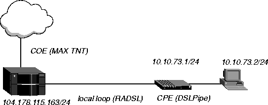
In Figure 14-3, a DSLPipe connects to a MAX TNT RADSL card over a PPP connection. The RADSL card is in slot 7 and the DSLPipe is connected to port 3 of the RADSL card. The DSLPipe IP address is 10.10.73.1/24. The MAX TNT IP address is 104.178.115.163/24.

Figure 14-3. Sample RADSL PPP connection
Configuring the ADSL profile
To configure the ADSL profile in this example:
- Read in the ADSL profile:
admin> read adsl-cap {1 7 3}
- List the profile:
admin> list
- Enable the port:
admin> set enabled=yes
- List the contents of the line config profile:
admin> list line-config
- Assign this port to a nailed group:
admin> set nailed-group=73
This nailed group points to the Connection profile you will create later. The nailed group must be unique for each active WAN interface.
- Specify the maximum downstream rate:
admin> set max-down-stream-rate=7168000
- Write the profile:
admin> write
Configuring the Connection profile
To configure the Connection profile in this example:
- Create a new Connection profile:
admin> new connection con7-3
- List the profile:
admin> list
- Enable the profile:
admin> set active=yes
- Set the encapsulation type to PPP:
admin> set encapsulation-protocol=ppp
- List the IP options submenu:
admin> list ip-options
- Set the IP address of the DSLPipe connecting to the MAX TNT:
admin> set remote-address=10.10.73.1/24
- Verify that IP routing is enabled (the default) for this Connection profile:
admin> set ip-routing-enabled = yes
- Verify that VJ header prediction is not enabled (the default) for this Connection profile:
admin> set vj-header-prediction = no
- List the PPP options submenu:
admin> list .. ppp-options
- Specify the authentication mode the MAX TNT requests for the outgoing call:
admin> set send-auth-mode = pap-ppp-auth
- Specify the password the MAX TNT sends to the DSLPipe:
admin> set send-password = pap
- Specify the password the MAX TNT expects to receive from the DSLPipe:
admin> set recv-password = pap
- Verify that the PPP address and protocol field compression is not enabled for this
Connection profile (the default):
admin> set acf-comp-enabled = no
admin> set pf-comp-enabled = no
- List the Telco Options submenu:
admin> list .. telco-options
- Specify the Call Type:
admin> set call-type= ft1
- Specify the nailed group to use for this Connection profile:
admin> set nailed-groups = 73
- Write the profile:
admin> write
Configuring the DSLPipe
To configure the DSLPipe in this example:
- From the Main Edit menu, select Configure.
- Specify the following values:
Chan Usage=Leased/Unused
My Name=con7-3
My Addr=10.10.73.1/24
Rem Name=cala-23
Rem Addr=104.178.115.163/24
Route=IP
Bridge=No
- From the Main Edit menu, select Ethernet >Connections > cala-23.
- Specify the following values:
Active=Yes
Encaps=PPP
Bridge=No
Route IP=Yes
- Open the Encaps Options submenu.
- Specify the following values:
Send Auth=PAP
Send PW=PAP
Recv PW=PAP
Link Comp=None
VJ Comp=No
- Open the Telco Options submenu.
- Set Call Type=Nailed.
- Exit the Connection profile and save your changes.
![[Top]](../images/home.jpg)
![[Contents]](../images/contents.jpg)
![[Prev]](../images/previous.jpg)
![[Next]](../images/next.jpg)
![[Last]](../images/index.jpg)


techpubs@eng.ascend.com
Copyright © 1997, Ascend Communications, Inc. All rights
reserved.

